Gold electroplating in the cleanroom
Cleanroom Tips | | Links: Cleanroom Labware | NFC
Gold electroplating is an important process in GaAs IC fabrication, but assembling a setup from scratch can be a daunting task for the inexperienced grad student (me!). Wikipedia provides a good intro on the basics of electroplating. I have developed a gold air bridge process with the electroplating approach detailed below.
The plating setup conisists of the following components:
- Gold electroplating solution
- Heated and agitated bath
- Wafer holding jig
- Platinized mesh anode
- Pulsed current source
Gold electroplating solution
When plating with a photoresist mask, sulifite-based plating solution provides more compatibility than traditional cyanide-based solutions. I had originally used Technic Elevate Gold 7990 as it was generously given to me by another research group, but the solution expired, giving poor results. I then moved to Transene TSG-250, another sulfite-based plating solution, as my group had used this in the past. The recommended current density is 1 to 8 ASF (amps/ft²), where ASF is roughly equivalent to mA/cm². The suggested optimum temperature for plating with TSG-250 is 60°C.
Heated and agitated bath
If you aren’t fortunate enough to have a wafer plating bench with heated bath, you will need a way to heat and agitate the plating solution. Perhaps the easiest way is simply a beaker on a hotplate-stirrer. A teflon coated bar is rapidly rotated by the stirrer, providing vigorous agitation. Unfortunately the hotplate-stirrer in my lab did not have a thermocouple or external probe, making it difficult to repeatably heat the solution to temperature. My solution was to use a simple stirrer and combine it with a heating element. While this solution works fairly well, the best solution would be a hotplate-stirrer with external thermocouple.
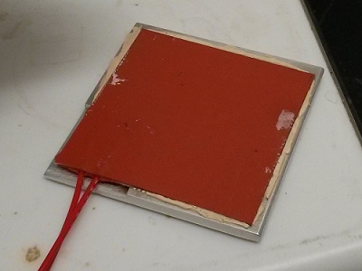
The heatpad is a 2”x2” 40W flexible silicone rubber heater sold by Omega (model SRFG-202/10). I bonded this to a similarly sized piece of aluminum using some thermal epoxy, with a recessed pocket milled out so it would sit flat. I also bonded some small pieces of glass slide to the backside of the aluminum plate to thermally insulate it from the stirrer it rests on.
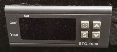
The heatpad is driven by 110 Vac, so I used a cheap temperature controller which provides power to the heatpad until the thermocouple reports the desired temperature (60°C), and then intermittently powers-on to maintain that temperature. To avoid contamination, I placed the thermocouple in a test tube filled with water, which I then placed in the plating solution. The temperature inside the test tube was within a degree of the plating solution.
Wafer holding jig
The wafer holding jig can be as simple as a suspended alligator clip or as complicated as a vacuum or compression gasket. If you just use an alligator clip, you will need to coat the backside of the wafer with photoresist as otherwise the backside will plate, even for semi-insulating substrates, and even without the seed layer. If this backside plating won’t affect your device/circuit operation, then a simple suspended alligator clip might be the easiest option.
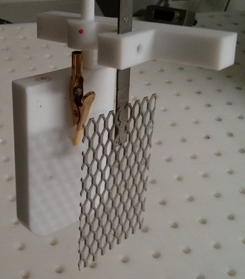
My first holder used vacuum and a viton gasket to hold the wafer and protect the backside, but an imperfect seal allowed solution to be suckedt through the seal. Actually, my very first holder used a viton oring, which promptly cracked the GaAs wafer when vacuum was applied! I settled on a simple teflon block with the alligator clip holding the wafer in place. The backside of the wafer will still get partially plated, but for now this works. The alligator clip had a jaw removed with a dremel, and then it was screwed into the teflon block.
If the wafer to be electroplated is covered with photoresist (to selectively plate features), then the area where the alligator clip contacts will need to be cleaned of photoresist using acetone and a swab.
This wafer holder will be subject to revision, as time allows.
Platinized mesh anode
A platinized titanium mesh is an economical anode, though you can use a pure platinum mesh if you have money to burn. Cheap platinized titanium mesh anodes can be bought from Amazon, if you trust them. Otherwise spend a bit more and buy from a dedicated plating supplies store.
Pulsed current source
Electroplating can be done with constant current source or a pulsed current source. Pulsed current plating is superior but requires a more complicated current source. Constant current plating can be achieved using a lab power supply in current limited mode. A pulsed current source requires a programmable supply (like the Keithley 220) or a bit of soldering to make your own. I wanted faster switching speeds than supplies like the Keithley 220 could achieve, so I built my own supply using the Linear 3092 current source IC. This source can provide more than enough current with slew rates fast enough for kHz pulse rates.
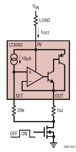
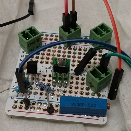
The circuit was crudely soldered together on a prototyping board, and the current can be adjusted with the potentiometer (Rpot, taking the place of the 20kΩ resistor). Output current is given by 10μA * Rpot / 1Ω. The load resistor in the circuit represents the two electrodes.
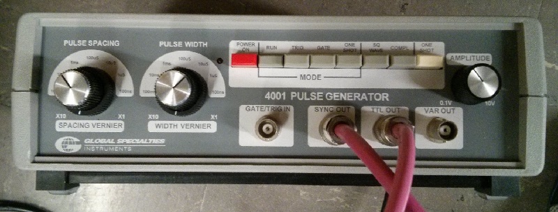
The current source circuit is modulated using a voltage pulse generator. Initially I used a simple 555-based square wave generator bought off eBay, but then I upgraded to a GSI 4001 Pulse Generator to give more control over the pulse duty cycle.
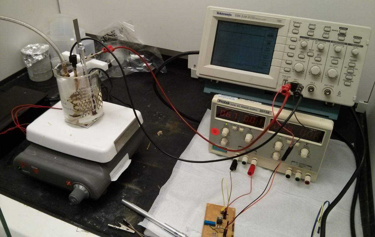
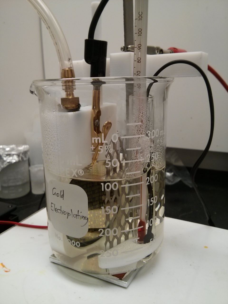
The complete setup
All these components come together to form the gold electroplating setup. The pictures below show an old verison of the setup, but provide a good picture of how everything works.
The complete electroplating setup in action!
Results
More images to come, but the site background image shows plated gold air bridges.